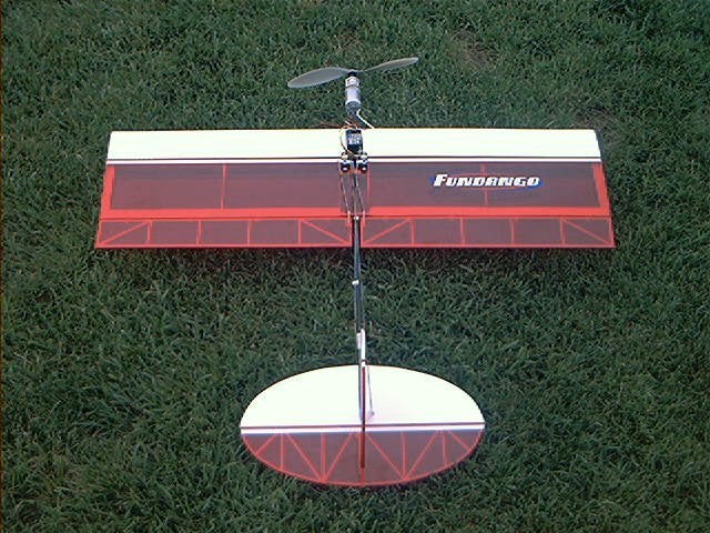
Tuesday, April 08, 2008

Great Planes Fundango

Great Planes Fundango
 
1 Attachment(s)

fundango

Specifications:
  • Wingspan: 35 in.
  • Wing Area: 350 sq. in.
  • Flying Weight: 13-16 oz. (advertised), 18 oz. (actual with gear)
  • Airfoil: Symmetrical
  • Motors used: Great Planes Electrifly T-400GD motor system (Speed 400 7.2-8.4 volt motor, 1.7:1 ratio gearbox
  • Prop: 10x7 APC electric propeller
  • Cells: Electrifly 9.6v 700mah NiCad battery pack (separate)
  • Speed Control: Electrifly C-20 high frequency ESC
  • Radio and gear: Hobbico CS-15 sub-micro servos (15.1 oz. torque), Hitec 555 receiver, Hitec Eclipse transmitter
  • Manufacturer: Great Planes
  • Available from: Tower Hobbies

Since this is my first review for the E-Zone, allow me to introduce myself. My name is Kevin Petrilla.  I have been involved in R/C since late 1993.  My initial interest in the hobby was with glow aircraft.  I still have some, but lately my interest has shifted significantly into the electric realm.  I quickly became the electric guy at the field.  My glow fuel consumption was ¾ of a gallon last year, which is down from about ten gallons a year from previous years.  Like many of you, I find electric aircraft to be more exciting, challenging, and a little less messy.

I should state that for the purpose of this review, the airframe, power system, battery, servos, and covering were supplied by the manufacturer/distributor.

Kit, monokote, and servos Electrifly

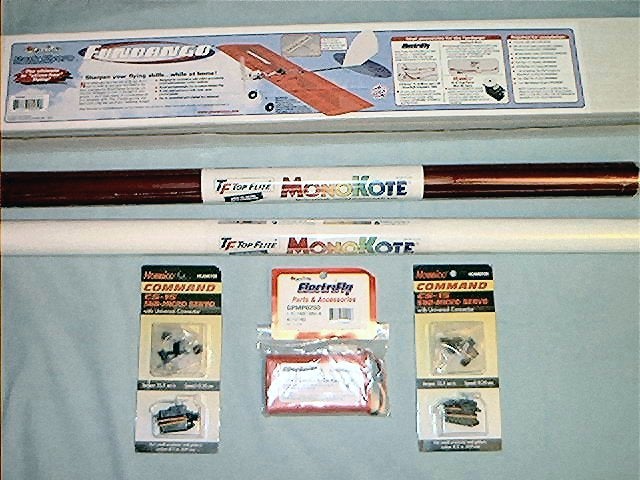
Instruction manual and plans

The first thing I do after opening the box is to pull out the instruction manual and read it from cover to cover.  The instruction manual is typical Great Planes quality, being easy to read and having excellent construction pictures. There is also a lot of information regarding equipment selection and building notes.  After reading the manual, I pulled out the plans and went over them as well.  Again, the plans are of very high quality and are easy to read.  The plans are on one sheet and all information is on one side, which is a definite plus.

Kit contents

Kit contents

Construction

Building the wing

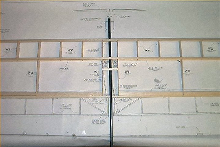
After checking to make sure all parts were there, I began to construct the wing. The wing construction is rather simple and very effective.  The vertical sheer web is one piece and the ribs are twisted and "locked" into place on corresponding notches in the web.  The notches ensure correct alignment and spacing on the main web. After the ribs are attached to the web, the bottom spar is added to the assembly.  Next, eight half ribs are added to the front of the web spar assembly. There are only six full ribs that make it from the front of the wing to the trailing edge of the wing.  Next, the leading edge, the bottom spar, and trailing edge are glued in place.  Pieces of 1/16 x 1/2 inch balsa are glued in place next in order to form an inner frame on the sides and trailing edge of the wing.  Plywood supports for the fuselage tube are now added to the wing.  Before the fuselage can be attached, a hole is drilled in the leading edge of the wing and a notch is cut in the trailing edge of the wing.  Now the fuselage tube can be test fitted.  The first thing that crossed my mind the when I picked up the fuselage was how heavy it was! The fuselage is made from heavy fiberglass tube, which could potentially be substituted for significant weight savings.  It should be easy to substitute a hollow carbon fiber shaft in place of the fiberglass shaft.  At this stage, wing construction is almost finished.  The next steps consist of framing up 3/16 x 3/16 inch balsa sticks to form the ailerons and then adding control horn support braces to the structure. My total building time to this point was just over two hours. Although the wing is simple to build, it became evident during construction that it would be sufficiently strong.  The only problem I encountered while building the wing was a small problem with the die cutting of the ribs.  The die cutting was a little shallow and it took some extra time with an Exacto knife to relieve the parts from their sheet.  In addition, some of the ribs and web were cut from varying densities of wood.

Wing over plans Wing and fuselage

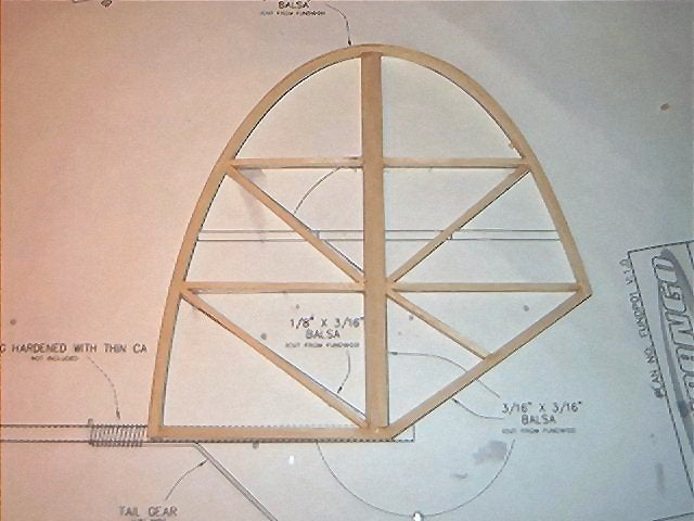
Building the tail surfaces

This is where the kit gets interesting! Unlike some kits where the frames of the tail surfaces are built first and then supported with inner structures, the tail surface supports for the Fundango are built first and then framed with laminated balsa strips.  I started by gluing 1/8 x 3/16 balsa sticks together over the plans to form the inner cross brace structure for the fin.  Once the inner structure is completed, you "move through the steps of wrapping the laminated frame of the fin."  Ok, this does not look easy I thought, but for the sake of the review, I must do it as they say.  T-pins are placed along the inside perimeter of the fin detail on the plan. Three 1/16 x 3/16 balsa sticks are glued, one at a time, to the outside of the framework while following the outline created by the pins.  Glass cleaner with ammonia is used to wet the wood in order to help it soften so it could be bent around the framework.

The pins sounded like a great idea, but as I began to laminate the framework, they were putting small creases in the wood, which did not give the appearance of a smooth curve.  I began to wonder if the pins were even necessary since it seemed so easy to bend the wood and glue it to the framework.  I removed the pins and re-laminated the section I had previously started, following the curve on the plan as I went.  I was rewarded with a nice smooth curve and it was much easier than it looked.  Two more strips of balsa were then laminated to the outside of the previous lamination using thin CA.  I deviated from the directions slightly at this point.  I knew that I would be using the landing gear on my Fundango for taking off, so I incorporated a rudder into the fin.  I placed one extra vertical support in the fin right next to the one already called for on the plans.  After the fin dried, I cut the fin in half between the two vertical posts, thus creating a fin and rudder.

The horizontal stabilizer is created with the same techniques as used above for the vertical fin.  After a complete stabilizer unit is built, the elevator is cut free from the stabilizer.

The process of gluing three consecutive laminations together does add a little extra weight to the tail surfaces, but it also adds strength, which would prove important during the covering process. There might be a tendency to skip the laminating process for a more convention construction method, but it is not necessary.

vertical stab horizontal stab

Assembling the fuselage

Even though the fuselage is just a tube, there are some steps necessary to prepare it to be used in this model. First, a slot must be cut into the rear of the fuselage in order to "slip" in the vertical fin.  A Dremel tool with cut-off wheel proved perfect for this step.  The fin is then temporarily installed and the tube inserted into the wing in order to set the correct alignment between the fin and wing. Next, a small wooden dowel is glued into the front of the fuselage.  This will eventually serve as the mounting surface for the motor mount.  Trailing edge reinforcement plates are installed now in order to secure the fuselage in the center of the trailing edge of the wing.  I then sanded the front of the fuselage and mounting dowel at an angle to provide the proper down thrust for the motor and gearbox.

I then came to a part in the instruction manual that said, "building the landing gear (optional)."  There was no option.  I needed gear! Besides, who wants to land on a 10-inch prop that does not fold?  The gear is fabricated from 1/16th inch wire that is bent to the specific angles that are outlined on the plans.  The main gear is then cut in half and inserted into holes that are drilled in the side of the fuselage tube.  The gear is held in place by wrapping string or thread around the gear and fuselage and then gluing the whole thing in place.  The tailskid is attached near the end of the fuselage in the same manner as outlined above.  The gear seemed a little flimsy, but only time would tell.

Airframe unassembled Bare airframe with gear from side

After completing construction of the sub-assemblies, I only needed to cover and assemble the model. After sanding the airframe, I began to cover it with Monokote.  I will not go into the covering, but I will say that applying the transparent red Monokote proved to be more difficult than the white that was supplied.  I have been covering models with Monokote for over eight years and this was only the second time I have had even the smallest problem.  To put it simply, the red just did not seem to want to shrink that easily, but the white was perfect.  After the model was completely covered, I began to put it all together.  A battery hook is fabricated from leftover wire, which is installed in a hole drilled just in front of the wing leading edge.  A rubber band is then stretched from the hook to the fuselage tube just behind the main wing's trailing edge.  When installed, the battery fits between the wing and the rubber band.  The ailerons, rudder, and elevator are easily hinged and installed.  Next, the control horns and wheels are installed.  The airframe was complete and it finally looked like a Fundango.

Covered airframe top Covered airframe

Mounting the motor and radio system

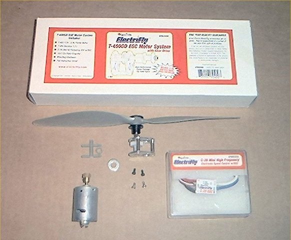
Note: The manual that I received says the Electrifly-400GD system includes a T-400motor, 3:1 gearbox, and 10x6 prop. The Electrifly system as provided for the review included a speed 400 motor, a 1.7:1 gearbox, and a 10x7 prop.

The motor and gearbox were attached to a motor mount that was assembled from two 1/16th inch pieces of plywood glued together. The only problem was that the screws that were supplied to connect the box, mount, and motor were too short.  I went to my "junk box" to find longer screws. After the gearbox and motor were attached to the mount, I attached the ESC to the motor.  This whole assembly was then screwed into the dowel in the front of the fuselage tube.  The indicted thrust angle was then set with a spacer made from leftover balsa.  A strip of tape was wrapped around the motor and fuselage to hold everything securely.  I then installed the 10x7 prop.

Mounting the servos consisted of placing them in their respective spots and securing them with screws.  Although the instructions say to place the receiver in the wing through the servo bay, I opted to mount mine on the top of the wing for easy access.

Here is where it gets interesting again.  The pushrods are made from 1/16th aluminum tube and .76mm wire.  The wire is cut and then glued in the ends of the aluminum tube.  After the wire is glued in the tube, Z bends are added to the wire to form the completed pushrod.  It sounds easy and it was, but I would not trust these rods to push a housefly out the front door.  First off, they proved to be too flimsy.  Secondly, the wire used in for the pushrod was smaller in diameter than the holes in the servo arms thus creating slop in the linkages.  The picture used to depict this construction sequence in the instructions clearly showed that their wire had slipped from inside the aluminum tube. (Page 20.  Photo 12) I definitely did not want mine to slip. I decide to go with a single piece of a larger diameter wire.  I cannot recall the exact size, but I took my servo horn to the local hobby shop and matched the diameter of the hole.  Early in the review, I stated that I added a rudder to the fin.  While I did add a rudder, it is activated with the aileron servo. I ran a third control rod from the aileron servo to the rudder.  When right aileron input is given, slightly less right rudder is given at the same time since it is connected farther in on the rudder control horn. I also added a pushrod support half way down the fuselage to keep the pushrod from buckling.  Now that everything was now ready to go, it was time to get ready to fly.

Fundango over concrete Fundango grass side Fundango grass top

Preparing the Model for Flight

The model was balanced 3-1/16th inches from the leading edge with the battery pack installed.  The battery pack had been slow charged the night before so it was already charged.  I hooked everything up and set up the control throws to one inch up and down on the elevator, and a half-inch up and down on the aileron.  I put the battery on the peak charger to charge the pack to capacity so I could do some static testing.

Static Tests (Recommended Motor System)

Having been involved in e-flight for some time now, I initially felt that the recommended power system just did not seem right.  The 1.7:1 gearing seemed very low for the recommended 10x7 prop and it was!  Here are the readings for the recommended setup, all of which were taken with an AstroFlight WhattMeter.

Cells x 8

AMPS

Watts

Initial voltage

Voltage drop

700 AA

15

99

10.5

6.8

500 AR

20

150

10.7

7.4

The numbers looked good, but not for a speed 400 motor.  The problem is that much of the "power" is being used to heat the motor.  The motor was so hot that not only did spit sizzle, it boiled away almost immediately.  I knew I was pushing my luck at this amperage, but since this was Great Planes recommended system, I took it to the field.

Fundango.jpg

Flight Tests

Electrifly Test Flights

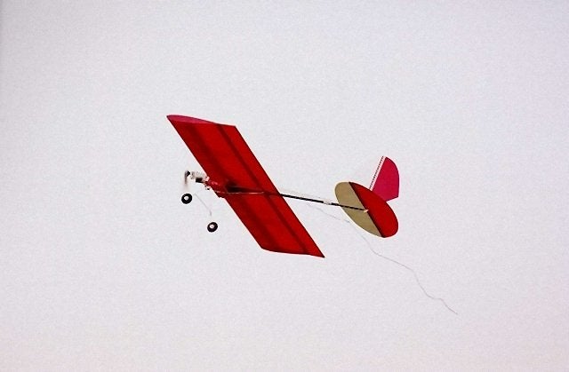
Once at the field, I took the obligatory flight line photos and prepped the plane for flight.  I set the plane on the runway and slowly applied power.  The Fundango came on step and lifted the tail surfaces in about 15 feet.  It was off in just over 20 feet.  After liftoff, it immediately wanted to nose down.  I kept feeding in up trim until it leveled off.  After I had it trimmed and flying level, I began to feed it more throttle. The extra throttle seemed to have no effect.  It had enough power to fly, but that was about it.  I slowly gained some altitude so that I could get a feel for its flying characteristics.  After a longer than anticipated climb to "three mistakes high," I pulled the power back to get a feel for its slow flight characteristics.  The nose dropped almost immediately without any snapping tendencies.  I knew that I would need some power in order to bring it in for a smooth landing.  Next, I tried a loop.  It would not loop from level flight, so I put it in a shallow dive and tried a loop.  The loop was easy with no tendencies to snap out of it at any point. I then gained a little more altitude to try some rolls.  The low rate rolls were uneventful and slow.  There was a small tendency for it to slow in the roll as the battery reached the top and then speed up as the battery came back around to the bottom. The high rate rolls were better as they had a much more fluid motion throughout the roll and happened much more quickly.  At this point, I had been in the air less than 3 minutes when the BEC kicked in.  I pulled the throttle back and then advanced it slowly to get some power back to the prop.  The Fundango settled in on the gear and then proceeded to go up on its nose as the gear collapsed under it.  I picked the plane up off the field and the gear sprung back to its original position.  The motor and battery were extremely hot!  There was only one word to describe the first flight, disappointing.

While the battery and motor were cooling down, I decided to see why it took so much up trim to get it to fly level.  I initially thought that the center of gravity was off.  However, after testing it again twice, I felt confident that it was right on.  At this point, it became very evident that all that down thrust was pulling the nose down thus forcing me to dial in all that up trim.  I wanted to change the thrust angle, but I did not have a way to do it at the field.

For the second flight, I switched over to the 500ar pack.  I knew that the amperage was very high, but I wanted some extra power.  The second flight was a little better.  It lifted off and got onto step quicker.  It could now just barely loop from level flight and the rolls were a little crisper due to its increased flight speed.  I was a little happier, but not much.  The BEC kicked in rather quickly.  I had been in the air only about 2 minutes, but I knew it would not last too long on the 500ar pack.  It was beginning to get dark so I packed up and headed home.

Overall, I was disappointed, but I felt that this airframe could be fun if it had the proper power system.  I subsequently flew the recommended motor combo with a 9x6 electric APC prop. Although the plane did pick up some speed, the thrust seemed down.  It flew similarly to the original combo, but flight times were up.  Here are the numbers with the 9x6 prop.

Cells x 8

AMPS

Watts

Initial voltage

Voltage drop

700 AA

11.8

78

10.7

6.7

500 AR

16

128

11

7.8

SpeedGear 480 Test Flights

I had enough of the recommended power system; so I went with something I felt would do this plane some justice.  It was time to put the fun in Fundango.  I went with the Graupner SpeedGear 480 from Hobby Lobby.  It consists of a speed 480-race 7.2v motor and a 3.34:1 gearbox.  I used the APC 10x7 prop that came with the original power package and some 8x800ar cells.  I also removed almost all of the down thrust that was originally put in the motor mount. I ran the numbers to get a feel for what was in store and here is what I found.

Cells x 8

AMPS

Watts

Initial voltage

Voltage drop

800 AR

18.8

167

11.1

8.6

950 AAUL

17

139

11.3

7.8

The numbers looked very promising so I packed up and headed to the field.  The initial flight with the new combo was inspiring.  It took off in less than ten feet and climbed with authority!  Before the flight, I set the elevator back to neutral since I had taken out the down thrust.  This proved to be right on.  Now, only a small amount of up trim was needed to fly level.  Loops were now very large.  There was no need to dive for speed anymore. Rolls were also much improved due to increased speed and thrust. I now felt more confident behind the sticks.  I tried multiple loops, rolls, Cuban 8's, Immelmans, and whatever else I could think to try.  Flight times were also longer because there was no need to run at full throttle constantly anymore. To say that I was now excited was an understatement.

Comments and Conclusions

First, I would like to comment on the quality of the additional components that were provided for this review.  The Great Planes CS-20 ESC that was provided was a big highlight in the flight of the model.  It performed flawlessly.  It is easy to operate, comes with a switch, and provides exceptionally smooth throttle response!  The Hobbico CS-15 servos also performed as intended in this setup.  The provided battery pack proved to be adequate for this application.  It had some limitations due to the high current draw.  If it were to be used in lower power applications, I am sure it would perform somewhat better.

The Fundango is a low hassle, fun to build airplane.  Some of the building techniques used might be different from what some of us are used to, but they proved to work fine.  I would not recommend the suggested power system. However, if you are looking for an aerobatic fun-fly type plane, the Fundango definitely fits the bill with a motor system upgrade.

Piper J3 Electricub ARF Review


Great Planes Piper J3 Electricub ARF Review
 
19 Attachment(s)

Introduction


Model Specifications
Wingspan: 41"
Length: 29.5"
Wing Area: 269 sq in
Weight: 14 oz
Wing Loading: 7.5 oz/sq. ft.
Motor: T-280 with 3.5:1 gearbox (Supplied)
ESC: Great Planes C-5 (Supplied)
Battery: Great Planes 8-Cell 600mah NimH (Supplied)
Prop: 10x7 (Supplied)
Manufacturer: Great Planes Model Manufacturing Co.
Available From: Great Planes Dealer Locator or Tower Hobbies online
Requires
Servos: 2 x Micro
Receiver: 3-Ch minimum
Transmitter: 3-Ch minimum
Charger(s)
Hand tools
Adhesives
As Reviewed
Servos: 2 x GWS Pico BB
Transmitter: Futaba 8UHPS
Receiver: Berg 5
All Up Weight: 17.25 oz
Wing Loading: 9.2 oz/sq. ft.

You've got your first trainer well under control. You can take off, circuit, and land without any mishaps, and you're starting to think about your next aircraft. You know that the super-scales and hot aerobatics planes are still a little way off. So what to get? Well, how about the Great Planes J-3 Electricub? It's an ARTF (ARF to you Americans) for easy assembly, it includes the power system (but not the radio gear), it has the three channel control system that you've trained on, and it has a nice semi-scale look to boot. Need further convincing? Well it's an unwritten rule that every R/C Pilot must own and fly a Piper Cub at some stage :). Great Planes market this nice looking park flyer specifically at the 'second aircraft' segment of the market. So let's take a look at it and see how well it fills its niche.

Kit Contents

The motor, gearbox, ESC, battery and prop are all included in with the kit. This is a great idea! It removes the guesswork normally involved in working out what powerplant to use, and is a feature that beginners to electric flight will really appreciate. But it doesn't include the radio system, which you already own from your trainer, so why pay to buy another! Just add your own servos, receiver, transmitter, and charger(s) and you're in business!

The Great Planes J3 Eletriclub is an ARTF, which is pre-constructed using traditional Balsa/Ply methods. All the major components are built and covered. Just final assembly and fitting of your electronics is required to complete the aircraft ready for flying.

As you can see from the photographs, the kit is extremely comprehensive, and even includes such 'extras' as velcro strapping for securing the electronics and rubber bands for the wings. A few hand tools, adhesives, and radio equipment are all that is required to finish it. The quality of assembly was excellent, with no warping, and no badly fitted parts evident through the translucent Cub Yellow covering. Only a few odd wrinkles marred a near perfect covering finish.

Assembly

As mentioned, this aircraft is an ARTF, so even a blow-by-blow is going to be a short write-up!

The comprehensive instruction manual runs to some 20 pages. The manual caters well to the beginners' needs with a lot of supplementary information covering balance, safety, pre-flighting and some basic flying hints. Each stage of the aircraft's construction is described in detail with copious supporting B&W photographs.

Wing

After gluing the panels together, I decided to tidy up the wing joint by wrapping a single layer of black tape around it.

Fuselage

The fuselage was a little more involved. I installed the landing gear and wing dowels, cleared the cooling holes in the removable battery cover (most important!) and installed the cover latch. That pretty much finished the fuselage!

Tail

One of the most important items in terms of affecting the handling of the aircraft, and consequently an area that it pays to take your time over, is mounting the tail. The method for aligning the stab was well documented in the manual, but I thought it worth while to photo it here as well.

OOPS!

This is one of the few areas of the aircraft that I wasn't 100% happy with. The fit of the fin/rudder actually fouled the movement of the elevator. I ended up trimming a little out of the elevator to give some clearance, but in retrospect it would have been better to shorten the rudder tab where it inserts into the tail plane.

Radio & Power Plant Installation

The radio installation took nearly as long as building the rest of the aircraft! I guess you tend to get that with ARTFs. I must admit I had a bit of a struggle getting the esc servos and receiver suitably located and fixed. This wasn't an issue with the aircraft though, just me and my big ham fists :). After a little manipulation, everything was in place and ready for final setting up.

Setting up Control throws and Centre of Gravity

Great Planes went to great lengths to ensure that you set your Electricub up correctly. Dimensions are given for all of the critical items, which I have listed in the table below.

Elevator Throw 5/8" Up and 5/8" Down at High Rate 1/2" Up and 1/2" Down at Low Rate
Rudder Throw 5/8" Right and 5/8" Left at high rate 3/8" Right and 3/8" Left at Low Rate
If no dual rates USE LOW RATES ONLY FOR FIRST FLIGHTS
Centre of Gravity Initial - 2-1/16" back from wing leading edge Alter by +/- 1/4" to suit once familiar with handling
Dihedral 3-3'4"

If you have radio equipment capable of dual-rates, Great Planes supplied throws for both high and low rates. They suggest that you use the low rates for your initial flights, and then move over to high rate as you become competent flying the aircraft. If you don't own a dual rate radio they recommend that you set your throws at the low rate setting initially.

Great Planes also strongly recommend that you use the suggested initial CofG balance point. One you are familiar with the aircraft, you can move it up to 1/4" forward or backward of the start point but never go outside of that range.

One other key point highlighted in the manual, sadly lacking in many other kits, is the importance of checking lateral balance as well as the fore/aft CofG. This is done by lifting the model by the prop shaft and the tail end of the fuselage and checking if either wing consistently drops. If one wing always drops when you do this, you need to balance the aircraft by adding weight to the 'high' wing until neither drops consistently.

Completion

After installing all the electronics, there was very little left to be done. The addition of the canopy and cowling went without issue. The instructions indicated that the two holes in the cowling would need to be cut out, but on the review example this had already been done.

I affixed the decals, using the box photo as a guide. I also decided to extend the black trim theme from the wing centre, and ran a matching strip down the top of the fuselage. An added bonus from this was that I now had a very quick visual check that my wing was correctly fitted and centred!

The final touch was to make up and fit the the simulated wing struts. These struts were simply yellow cord strung between ply mounting plates on the wings and fuselage. Although they provided no structural gain to the aircraft at all, along with the realistic decals they certainly helped to create 'the look' of a Piper Cub.

Final Centre of Gravity Check and Flying Weight

A final check of the Centre of Gravity showed it to bit a little too far aft compared to the recommended position. I ended up adding 0.8 oz of weight at the firewall to bring the CofG into the correct starting position.

The all up weight was a little over the advertised 14 oz. Mine came in at 17.25 oz completed and ready to fly. This brought the final wing loading up to 9.5 oz / square foot.

Flying

All that was left now was to wait for suitable flying weather. And so I waited... And waited.... And waited.....for two and a half MONTHS!

Of all the times to have the worst summer weather in 140+ years, it had to be this year!

Having received the Cub in late October 2004, and having it ready to fly from the first week in November 2004, I ended up having to wait until mid January 2005 before we got conditions to maiden the aircraft. The sudden, unexpected break in the weather on the day I flew took place in the evening. So it was a full on rush to get out to the field and get some flights in before sun-set.

As a consequence, I'm afraid that this flying report will be a little short, and there are no in-flight photos and videos at this stage. With the indulgence of the editors, I plan to return to this review in a month or so. Hopefully this turn in the weather will continue long term. If so, I'll be able to get out and put more hours on the clock, and get some in-flight video and photos to fill this review out more completely.

Basics

First up I rigged the aircraft ready for flight and double checked the CofG, my control orientations, and ensured that I had my dual rate switches set to low rate. A quick run up of the motor to check that all was well, and it was off to the flight line.

Taking Off, Circuits and Landing

One look at the state of our strip (remember the weather I mentioned?) made the decision to hand launch easy. I ran the motor up to full power, gave Deane the nod, and with a gentle straight and level push we were off!

The little Cub left Deane's hands and flew away straight and true. The 280 motor in full song provided a healthy climb rate. There was no tendency to dip after leaving the hand launch, nor was the climb-out so steep as to get a newcomer into trouble.

Once I'd reached about 50ft altitude I made a gentle turn to the right. The Cub banked around nicely, with only a small amount of up elevator required to maintain altitude through the turn. Once I reached cruising altitude I found that I could throttle back to about 80% power and still maintain altitude and airspeed comfortably.

After cruising around for what seemed like forever (about 10 minutes according to the guys I was flying with) it was time to try a landing. Throttling back, I found that the Cub would keep flying right down to not much more than walking speed! I must admit that my landing skills were very rusty, but even my ham-handed approaches didn't phase the little Cub. I couldn't say that the plane is un-stallable, but I sure didn't find the limits despite being badly out of practice!

Speaking of airspeed, with the throttle at max, and a bit of down elevator to prevent a climb, the Cub is capable of a surprising fast turn of speed! It's quite a contrast to the extremely slow flying speed at the opposite end of the rage.

The only fault I really found with the Cub's flying characteristics was that the elevator response was pretty twitchy even when set at the lower throw rates. I will be reducing the throws on this and will report the outcome in the updated flying review.

I ended up getting three flights in before the light started to drop, and the wind started to come up again. As I settled back into 'fixed wing mode' I found each minute of each flight more and more relaxing. This little plane is a real pleasure to fly. It has sufficient power for a reasonable climb out, can fly so slowly that I could just about jog alongside it, and has very gentle handling. Once trimmed out, it will fly 'hands-off' just about forever!

The guys I were flying with were VERY impressed. They all commented on how nice the Cub looked in the air, and how well it handled. Another real bonus was the noise - or the lack thereof! This aircraft is really quiet. Even in the dead calm air, you could hardly hear it once airborne. It's definitely a very neighborhood-friendly park flyer!

Although time and conditions were against me testing it out, I suspect that a ROG take-off would be quite attainable from a smooth take-off surface. I also think that with some altitude and a dive to build up some airspeed, the Cub would be capable of pulling a loop. I hope to be able to test these ideas in the upcoming weeks, and hopefully report back here.

Is This For a Beginner?

OK, confession time... Although I have been flying MicroHelis for the past five years, up until today I hadn't flown a fixed wing aircraft for nearly 30 years! So although I have flying skills, I think I can just about qualify as a beginner again when it comes to fixed wing aircraft.

I started off this review looking at the Great Planes Piper J3 Electricub as a potential 'second aircraft'. Now, having built and flown it, I have to change my opinion! Provided that an experienced pilot was available to oversee/assist with construction, trimming and flight lessons, I would say that this aircraft would make a great first aircraft. It has a very forgiving nature and no nasty habits. The tiny 600mah battery pack seems to provide a good 10 minutes of flight, which is more than ample for the beginner.

As a few of my 'landings' demonstrated, traditional construction methods still stand up well in anything less than a full on crash. The worst I managed to do was bend the undercarriage legs back a little, and they were easily bent back into shape.

Conclusion

The Great Planes Piper J3 Electricub truly deserves to be called a Great Plane!

As a first aircraft for beginners (I recommend some expert assistance), second aircraft, or as a very pleasurable and relaxing park flyer, the Cub meets the requirements fully. The cub is a quick easy build and has everything you need except the radio gear.

My cub came out a little overweight, and the interference of the rudder post with the elevator was an annoying problem that would likely stump a beginner. I do still want to explore the elevator low rates further to see if a softer low rate, which would better suit a beginner, will still fly the model safely. Otherwise, perhaps some exponential is what the little cub needs around neutral.

It looks great, both on the ground and in the air, and flies beautifully. It's the ideal small aircraft to 'find' in the trunk of the car when you arrive at your destination on a family outing ;).

Flying Tutor

Pilot an R/C plane from the comfort of your own backyard, or at the park or playground — almost anywhere you wish. With the Great Planes Tutor, you'll have a feather-light trainer that's stable and slow-flying, but adds the potential to try basic aerobatics when you're ready. It also saves you building time, spending money and flying space. There's no better way to get your wings!

  • A park flyer with the style and look of full-size planes.
  • Surprisingly lightweight (9.5-13.5 ounces) and easy to transport.
  • Features a flat-bottom wing for trainer-like stability and instructions for adding optional ailerons.
  • A natural for Sunday sport flying or exploring basic aerobatics.
Please find the PDF format for the tutor at the link below..


Phatom Top view

Top View Phantom

Phantom

Great Planes Piper Cub J-3 60

Models

Carl Goldberg Super Chipmunk

F-4 Phantoms

 
Side view Construction


Front View
 

Great Planes F-15 Eagle

Carl Goldberg Super Chipmunk

Metric Dimensions


Two-Stroke Engines for Fixed Wing R/C Aircraft
  A B C D E F G H J S
10FP, 10FP-S 31.4 11 54 38 58.2 38.7 23 33.2 45.2 M5
10LA 31.4 11 54 38 56 38.7 23 33.2 45.2 M5
15CV-A 33 14.4 63.7 40 61 39.5 24.8 30.8 48.5 M5
15FP, 15FP-S 33 14.4 56.5 40 63.2 39.5 24.8 30.8 50.2 7/32-32
15LA, 15LA-S 33 14.4 56.5 40 61 39.5 24.8 30.8 48.5 M5
20FP, 20FP-S 36 14 66.5 45 74.5 46.5 29 39.5 60 1/4-28
25FP, 25FP-S 36 14 66.5 45 74.5 46.5 29 39.5 60 1/4-28
25FX 38 15 75.6 46 75.5 53 30 45.5 60 1/4-28
25LA, 25LA-S 36 14 67.5 44 74.5 46.5 29 39 60 1/4-28
25LA-S 37 15 87.1 48 74.4   28     1/4-28
30 Wankel Rotary     60.5 65.7 58.3         1/4-28
32SX 38 15 75.5 45 73 53 30.3 45.5 60 1/4-28
40FP, 40FP-S, 35FP, 35FP-S 40.5 17.5 74.2 48 82.2 51.2 32 42.5 66 1/4-28
40LA, 46LA, 40LA-S, 46LA-S 40.5 17.5 74.5 48 85 51.2 32 42.5 69 1/4-28
46AX 44 17.5 85.2 51 85.2 60.4 35   67.4 1/4-28
46FX, 40FX 44 17.5 85 51 88 60.5 35 52 70 1/4-28
46VX-DF RC 44   116   91   35     1/4-28
50SX 44 17.5 85.7 52 88.8 60.7 36   70.5 1/4-28
55AX 44 17.5 85.3 51 90.5 60.4 36 52 72 1/4-28
60FP 52 25 92 61 102 64 42 51.5 81 5/16-24
61FX 52 25 95.6 61 100.5 66.5 43 54 79 5/16-24
65LA 52 25 64 62 85.4 64 42   85.4 5/16-24
65VR-DF 52 25 133.5 61 101.7 66 43.4 53.5 79.7 5/16-24
91FX 52 25 96 61 103 66.5 42.6 54 81.5 5/16-24
91VR-DF 52 25 133.5 61 109.5 66 43.5 53.5 87.5 5/16-24
91VR-DF (small head) 52 25 133.5 61 103.5 66 43.5 53.5 81.3 5/16-24
1.08FSR 58 30 108 70 119 75 48 60 95 3/8-24
120AX 58 25 100.2 67 109.2 69.8 46.5   85.7 5/16-24
140RX, 1.40RX-FI 58 25 105 70 118.4 78 48.4   93.9 5/16-24
160FX, 1.60FX-FI 64 30 115.5 74 123.2 80 51.5   96.7 3/8-24
BGX-1 74 32 129.5 85 142.5 99 60.5 83 111 3/8-24
Single Cylinder Four-Stroke Engines
  A B C D E F G H J S
FL-70 45 20 103 54 107.5 59.5 35.4 49.5 89.5 1/4-28
FS-26 36 14 84 44 86.5 48.5 29 40 70 1/4-28
FS-30 36 14 112 44 86.5 75 29   71.5 1/4-28
FS-40 42 17.5 77.5 49 98 57 32.5 48.1 80.5 1/4-28
FS-52S, FS-52S Heli 44 17.5 80.5 51 101 59 34 49.3 83.5 1/4-28
FS-70 50 21 89 59 116.5 66 40 55.5 96 5/16-24
FS-70 II 50 21 111 58 116.7 66.3 39.6 55.8 96.4 5/16-24
FS-70 Ultimate-P 45 20 109.7 54 105.4 59.5 35.4 49.5 87.4 1/4-28
FS-91 52 25 91.5 60 121 66.5 42.6 54 99 5/16-24
FS-91 II, FS-91 II FI 52 25 114.5 60 123 66.5 42.6 54 101 5/16-24
FS-91S II-P 52 25 91.5 60 123 66.5 42.6 54 101 5/16-24
FS-120S-E 58 25 104 67 138.5 77 46 64.5 115 5/16-24
FS-120S III 58 25 134.5 67 139.5 77 46 64.5 116 5/16-24
FS-120S-SP 58 25 157 67 139 77 46 64.5 115 5/16-24
Helicopter Engines
  A B C D E F G H J S
32SX-H, 32SX-HX 38 15 75 45 76 53 30.3 45.5 60.6 1/4-28
32SX-MX 38 15 127.4 45 82.5 85.7 30.6   58  
37SZ-H 38 15 67.2 45 76.8 46 30.6   61 1/4-28
46FX-H 44 17.5 84.2 51 88 60.5 35 52 70 1/4-28
50SX-H 44 17.5 85.8 52 89 61 36   70.5 1/4-28
50SX-H Hyper 44 17.5 85.8 52 89 61 36 74 70.5 1/4-28
61LX-H 52 25   61   88.7 42.6   79 5/16-24
61RX-H WC 52 25 93 61 100.5 65 42.6 52.5 79 5/16-24
61RX-HG WC 52 25 80.5 61 100.5 52.5 43.6 40 79 1/4-28
61SX-H WC 52 25 93 61 100.5 65 42.6 52.5 79 5/16-24
61SX-HG WC 52 25 80.5 61 100.5 52.5 43.6 40 79 1/4-28
70SZ-H 52 25 81.3 61 99 55.3 42.6   77.5 5/16-24
91SX-H   25 82   109   42.6      
91SX-H C-Spec-P 52 25 109.4 61   56.4 42.6   87.4 5/16-24
91SX-H C-Spec 52 25 83.4 61     42.6   87.4 5/16-24
91SZ-H 52 25 83.8 61   56.4 42.6   87.4 5/16-24
91SZ-H PH-Hyper 52 25 97.5 61 119.2 64.4 43 51.9 87.4 5/16-24
FS-52S Heli 44 17.5 80.5 51 101 59 34 49.3 83.5 1/4-28
Marine Engines
  A B C D E F G H J S
10FP-M 31.4 11   38 64   23   51.5 1/4-28
10FP-MX 31.4 11   38 72       51.5 1/4-28
18CV-R-M 31.4 11 56 39   41 25   50.5 M5x0.8
20FP-M 36 14   45 76   29   61.5 1/4-28
21RZ-M 37 21   45 74.7   29.6   59.7 1/4-28
21VZ-M 37 21 65 45 89.1 44 30.8   73.8 1/4-28
32F-MX 38 15   45 87       63 1/4-28
46VX-M 45 21   53 87   37   68 1/4-28
61VR-M, .65 VR-M 52 25   61 104.3   43   84.3 5/16-24
81VR-M 52 25   61 105.5   43.4   84.1 5/16-24
Car & Buggy Engines
  A B C D E F G H J S
10FP-B 31.4 11 54 38 67 38.7 23 33.2 55 M5
10FP-BX 31.4 11 72.7 38 67 38.7   33.2 55 M5
12CV 31.4 11 58.6 39 87.2 41 25 35.5 74.4 M5
12CV 31.4 11 58.6 40 90.2 41 25 35.5 70.7 M5
12CV-R 31.4 11 70 39 83.7 41 25   70.9 M5
12CV-RX 31.4 11 88.8 40 90.9 41 25   70.9 M5
12CV-X 31.4 11 74.8 39 87.2 41   35.5 74.4 M5
12TG 31.4 11 58.4 39 89.5 40.9 25.4 35.4 77 M5
12TR (P), 12TR (P)-T 31.4 11 52.5 39 84.4       71.6 M5
12TR, 12TR R-Spec 31.4 11 58.5 39 85       71.6 M5
12TZ (P) T3 Speed Tuned 31.4 11 52.4 39 87 34.9 25.4 29.4 74.5 1/4-28
12TZ (P)-T3 ABC 31.4 11 49.9 39   34.8 25.4   77.2 1/4-28
12TZ (P)-T5 ABC 31.4 11 49.9 39   34.8 25.4   77.2 1/4-28
12TZ (S)-T3 ABC 31.4 11 49.9 39   34.8 25.4   77.2 M5x0.8
12TZ-T3 ABC 31.4 11 55.9 39   40.8 25.4   77.2 M5x0.8
15CV 31.4 11 58.6 39 90.2 41 25   70.7 M5
15CV-M 31.4 11 58.5 40 65          
15CV-MX 31.4 11 91 40 65          
15CV-R 31.4 11 56 39 83.9 41 25   71.1 M5
15CV-RX 31.4 11 74.8 40 91.1 41 25   71.1 M5
15CV-X 31.4 11 74.5 39 90.2 41 25   70.7 M5
15RX 37 21 60 45 87.3 41.5 29 31 72.5 1/4-28
18CV-R 31.4 11 56 39 100.9 41 25   80.9 M5
18CV-R (P) 31.4 11 49.9 39 100.9 41 25   80.9 M5
18CV-RX 31.4 11 74.8 40 100.9 41 25   80.9 M5
18TM 31.4 11 53.6 39   34.8 25.4   81.2 M7x1
21RG, 21RG (P) 37 21 65.6 45 95.8 44 29.6 33.5 80.7 1/4-28
21RG-B, 21RG-B (P) 37 21 65.6 45 95.8 44 29.6 33.5 80.7 1/4-28
21RG-M 37 21 88.5 45 74.5 67 29.6   59.5 1/4-28
21RG-MX 37 21 107 45 74.5 67 29.6   59.5 1/4-28
21RG-X (P) 37 21 84 45 95.8 44 29.6 33.5 80.7 1/4-28
21RZ-B, 21RZ-B (P) 37 21 79 45 101 44 29.6 33.5 86 1/4-28
21RZ-R (P) 37 21 65.5 45 96.3 44 29.6 33.5 81.5 1/4-28
21RZ-V99B, 21RZ-V99B (P) 37 21 65.6 45 101 44 30.6 33.5 86 1/4-28
21VG 37 21 65.6 45 102.7 44 30.8 33.5 87.4 1/4-28
21VZB V-Spec 37 21 64.9 45 110.6 44 30.8 33.5 95.3 1/4-28
21VZB V-Spec 37 21 64.9 45 110.6 44.3 30.8 33.8 95.3 1/4-28
21VZ-B V-Spec-T (P) 37 21 64.9 45 110.6 43.9 30.8 33.8 95.3 1/4-28
21VZ-R, 21VZ-R Turbo II 37 21 64.9 45 99 43.9 30.8   83.7 1/4-28
21VG (P) ES 37 21 65.6 45 102.7 44 30.8 33.5 87.4 1/4-28
18TZ (P) 31.4 11 49.9 39   34.8 25.4   81.2 1/4-28
18TZ Turbo 31.4 11 55.9 39   40.8 25.4   81.2 M5x0.8
18TZ(S) Turbo 31.4 11 49.9 39   34.8 25.4   81.2 M5x0.8
18TZ-TX 31.4 11 75.3 39   40.8 25.4   81.2 M5x0.8
30VG (P) 37 21 65.6 45   44 30.8   97.7 1/4-28
30VG (P) ES 37 21 65.6 45 113 44 30.8 33.5 97.7 1/4-28
30VG (P) SR Savage 37 21 65.3 45   44 30.8   97.7 1/4-28
30VG (P)-X 37 21 82.5 45   44 30.8   97.7 1/4-28
FS-26S-C 36 14 57.8 43 84.6 39.8 29 32.8 70.4 1/4-28
FS-26S-C II 36 14 57.8 43 85.4 39.8     70.9 1/4-28
 
FR5-300 Flat-Four cylinder Twin Cylinder
 
Twin & Multi-Cylinder Four-Stroke Engines
  A B C D E F G H J S
FR5-300 122     234 158.5         3/8-24
FF-320 68 56.5 23.5 196 181.5 112.5 125.5 76 62 5/16-24
FT-300 90 55 35 240 148 62 80 56 10 3/8-24
FT-160 68 56.5 23.5 196 120 50.5 63.5 54   5/16-24
FT-120II 68 56.5 23.5 196 120 50.5 63.5 54   5/16-24
IL-300 Dia-Star 76 40 50 116 234.3 173 113 48.6 40 3/8-24